Servo motors are a special type of motor that don’t spin around in a circle, but move to a specific position and stay there until you tell them to move again. Servos usually only rotate 180 degrees (one half of a circle). Servo motors are a special type of motor that don’t spin around in a circle, but
move to a specific position and stay there until you tell them to move again. Servos usually only rotate 180 degrees (one half of a circle)
 .
.To use the servo motor with Arduino, we will need some assistance from previously written codes known as libraries. One of the great things about the Arduino community are the talented people
who extend its functionality through additional software. It’s possible for anyone to write libraries to extend the Arduino’s functionality. There are libraries for a wide variety of sensors and actuators and other devices that users have contributed to the community. A software library expands the functionality of a programming environment. The Arduino software comes with a number of libraries that are useful for working with hardware or data. One of the included libraries is designed
to use with servo motors. In your code, you’ll import the library, and all of its functionality will be available to you.
We will be controlling the motion of the servo motor with a potentiometer.


(Source: Arduino Projects Book)
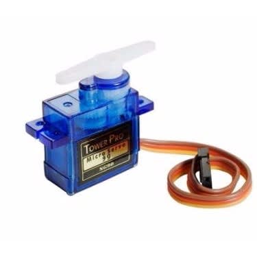
The servo has three wires coming out of it. One is power (red), one is ground (black), and the third (white) is the control line that will receive information from the Arduino. Plug three male headers
into the female ends of the servo wires (see Fig. 3). Connect the headers to your breadboard so that each pin is in a different row. Connect 5V to the red wire, ground to the black wire, and the white wire to pin 9. When a servo motor starts to move, it draws more current than if it were already in motion. This will cause a dip in the voltage on your board. By placing a 100uf capacitor across power and ground right next to the male headers as shown in Fig. 1, you can smooth out any voltage changes that may occur. You can also place a capacitor across the power and ground going into your
potentiometer. These are called decoupling capacitors because they reduce, or decouple, changes caused by the components from the rest of the circuit. Be very careful to make sure you are
connecting the cathode to ground (that’s the side with a black stripe down the side) and the anode to power. If you put the capacitors in backwards, they can explode.
The Code
This code exists in the examples of the Arduino IDE, navigate to File - Examples - 10.Starterkit_Basickit - p05_servomoodindicator.
Firstly, we import the servo library. Then we create a servo object, here we call it myservo. Next is variable declared for our potentiometer pin. In the setup(), you’re going to need to tell the Arduino what pin your servo is attached to. Include a serial connection so you can check the values from the
potentiometer and see how they map to angles on the servo motor.
In the loop(), read the analog input and print out the value to the serial monitor. To create a usable value for the servo motor from your analog input, it’s easiest to use the map() function. This handy function scales numbers for you. In this case it will change values between 0-1023 to values between 0-179. It takes five arguments : the number to be scaled (here it’s potVal), the minimum value of the
input (0), the maximum value of the input (1023), the minimum value of the output (0), and the maximum value of the output (179). Store this new value in the angle variable. Then, print out the mapped value to the serial monitor.
Finally, it’s time to move the servo. The command servo.write() moves the motor to the angle you specify. At the end of the loop() put a delay so the servo has time to move to its new position.
Now the operation; Once your Arduino has been programmed and powered up, open the serial monitor. You should see a stream of values similar to this:
potVal : 1023, angle : 179
potVal : 1023, angle : 179
When you turn the potentiometer, you should see the numbers change. More importantly, you should see your servo motor move to a new position. Notice the relationship between the value of potVal and angle in the serial monitor and the position of the servo. You should see consistent results as you turn the pot. One nice thing about using potentiometers as analog inputs is that they will give you a full range of values between 0 and 1023. This makes them helpful in testing projects that use analog input.
Now that you’re up and running with motion, it’s time to let people know if you’re available to help them on their projects, or if you want to be left alone to plan your next creation.
With scissors, cut out a piece of cardboard in the shape of an arrow. Position your servo to 90 degrees (check the angle value in the serial monitor if you’re unsure). Tape the arrow so it’s oriented in the same direction as the motor’s body. Now you should be able to rotate the arrow 180 degrees when turning the potentiometer. Take a piece of paper that is larger than the servo with the arrow attached and draw a half circle on it. On one end of the circle, write “Stay Out”. On the other end, write “Come in”. Put “Knock please!” in the middle of the arc. Place the servo with the arrow on top of the paper. Congratulations, you’ve got a way to tell people just how busy you are with your projects!

No comments:
Post a Comment