In the last post (here), we went through a list of some
components expected in an Arduino starter’s kit. Now we will continue from we
stopped and list more components and the function they perform with images to
identify them in the kit.
|
Potentiometer
- A variable resistor
with three pins. Two of the pins are connected to the ends of a fixed
resistor. The middle pin, or wiper, moves across the resistor, dividing it
into two halves. When the external sides of the potentiometer are connected
to voltage and ground, the middle leg will give the difference in voltage as
you turn the knob. Often referred to as a pot.

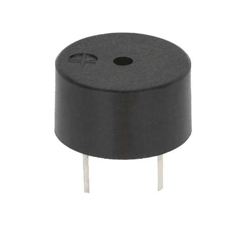
Piezo - An electrical
component that can be used to detect vibrations and create sound
Pushbuttons - Momentary switches
that close a circuit when pressed. They snap into breadboards easily. These
are good for detecting on/ off signals.
 |
USB Cable - This allows you to
connect your
Arduino Uno to your
personal computer for programming. It also provides power to the Arduino for
most of the projects in the kit.

Transistor - A three legged device
that can operate as an electronic switch. Useful for controlling high current/high voltage
components like motors. One pin connects to
ground, another to the component being
controlled, and the third connects to the Arduino. When the component receives voltage on the pin connected to an Arduino, it closes the circuit between the ground and the other component.
Sonar sensor:
Sonar or ultrasonic sensors are good at detecting objects in their
surroundings. The Sonar sensor we will be using is a Parallax sensor that uses
digital pinging to tell how far away an object is.

Servo motor - A type of geared motor that can only rotate 180 degrees. It is controlled by sending electrical pulses from your Arduino. These pulses tell the motor what position it should move to.
|
There are hundreds of
other components which we could interact with Arduino but it will be impossible
to go over all of them. As we proceed with building projects, we will become
familiar with these components. However, we need to understand certain concepts
which are the building blocks of electronics and robotics. Working
with an Arduino means working with both software and hardware, if you are
working with hardware, you’ll be using electricity to either sense something or
actuate something, or both. So understanding some of the basics of electrical
circuits is a good idea.
Electricity is a type of
energy, much like heat, gravity, or light. Electrical energy flows through
conductors, like wire. You can convert electrical energy into other forms of
energy to do something interesting, like turn on a light or make some sound out
of a speaker.
The components you might use to do this, like speakers
or light bulbs, are electrical transducers. Transducers change other
types of energy into electrical energy and vice versa. Things that convert
other forms of energy into electrical energy are often called sensors, and things that convert
electrical energy into other forms of energy are sometimes called actuators. You will be building circuits to move electricity through
different components.
Circuits are closed loops of wire with a power source
(like a battery) and something to do something useful with the energy, called a
load. In a circuit, electricity flows from a point of higher potential energy
(usually referred to as power or +) to a point of lower potential energy.
Ground (often represented with a - or GND) is generally the point of least
potential energy in a circuit.
In the circuits you are building, electricity only flows
in one direction. This type of circuit is called direct current, or DC. In
alternating current (AC) circuits electricity changes its direction 50 or 60
times a second (depending on where you live). This is the type of electricity
that comes from a wall socket.
There are a few terms you should be familiar with when
working with electrical circuits. Current (measured
in amperes, or amps; with the A
symbol) is the amount
of electrical charge flowing past a specific point in your circuit. Voltage (measured in volts; with
the V symbol) is the difference in
energy between one point in a circuit and another. And finally, resistance (measured in ohms; with the Ω symbol)
is how much a component resists the flow of electrical energy.
One way to imagine this is to think about a rock-slide going down a cliff, as shown below. The higher the cliff, the more energy the
rocks will have when they hit the bottom. The height of the cliff is like the
voltage in a circuit: the higher the voltage at the energy source, the more
energy you have to use. The more rocks you have, the more energy is being
carried down the cliff. The number of rocks is like the current in an
electrical circuit. The rocks go through bushes on the side of the cliff,
losing some energy in the process; the energy is used up to crush the bushes.
The bushes are like resistors in a circuit, offering resistance to the
electrical flow and converting it into other forms of energy.

There is a mathematical equation relating these 3
electrical quantities and we will look at that in the next post. Ciao!
No comments:
Post a Comment