So far so good, we have discussed only about robotics using Arduino
from the hardware point of view. It’s important to state that there are two
parts to understanding robotics. There is always the hardware; dealing with
components and circuitry and there is also a software
part of robotics which
deals with the logic and programming of the robot. To be well versed in
robotics, it’s essential we master both. Today we will dive into the software
aspect so that we can learn both the hardware and software simultaneously which
gives a complete meaning and understanding to robotics.
The Arduino is programmed in a language similar to C++ and
also copies some syntax from Java. The
first thing we need to do is download the Arduino IDE (Integrated Development
Environment) which is where we will be writing our codes and then uploading
them to the Arduino board. We can download the IDE on the Arduino website here.
You will find out that Arduino has a version for Windows OS, Mac OS and Linux
so whichever you use, you have no worries. Proceed to download the Arduino IDE
setup and install it. The installation is straightforward and simple.
Now that we have installed the Arduino IDE, proceed to
launch it from your desktop or launcher. You should have an interface similar
to the image below. You may have a more recent version of the IDE but mine
works fine as well! Lol.
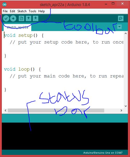
There are options in the
toolbar such as verify, upload etc. Let us open our first program called Blink,
to do this; Click File,
then Examples, then 01.Basics, and finally, Blink. So we have our blink program
on the screen now but there is something missing; we need to connect our Arduino
board to the computer via the USB cable and then design our circuit on the
breadboard. Luckily we know how to do this so let’s do it!.

Now we have connected our Arduino Uno (or any other Arduino board
or clone) and we have setup the circuit, lets return to our code. Next, you will need
to select your board from the list in Tools ➤ Board. For an Arduino Uno and Uno
clones, select this from the top of the list or you may even have a Leonardo, Mega or a DUE. Choose whichever
board matches yours. Then
we need to confirm the COM port our Arduino is connected. To do this Select the serial device of the Arduino board from Tools ➤ Serial Port. If you are not sure what your port is, disconnect the Arduino and
check the ports available, then reconnect the Arduino and see which port has
now appeared (you may need to close and reopen the menu to get it to show). By
this stage, we have our Arduino connected to the right port, we have selected
the right Arduino board and we have designed our circuit. All that is left is
to upload our Blink code, this is pretty straightforward, just click on the
upload button on the toolbar, it takes a few seconds or more depending on how
powerful your computer is. We see the progress and we see the words “Done uploading” on the
IDE status bar.
Looking at the LED in our circuit, we will notice it blinks ON/OFF
with a second interval; meaning it stays ON for one second and goes OFF for one
second. If you have this working successfully; congratulations, you have built
your first project. Let us rip open the Blink code so we understand why the LED
acts as such. The first couple of lines which appear faint in ash colour are
called comments; they do not affect the code and here we see the credits given
to the people who developed the Blink code. Depending on your Arduino IDE version, you may
see this;
int led = 13;
This is known as variable
declaration and this means a
fancy term that you need to type the names of each input or output that you
want to use in your sketch. You can rename an Arduino input/output pin number
with any name (i.e., led_pin, led, my_led, led2, pot_pin, motor_pin, etc.) and
you can refer to the pin by that name throughout the sketch rather than the pin
number. You can also declare a variable for a simple value (not attached to an
I/O pin) and use that name to refer to the value of that variable. Thus, when
you want to use the value of the variable later in the sketch, it is easy to
recall. These variables can be declared as several different types, but the
most common that we use is an integer (int). Other variable types are used in
later examples (i.e., float, long, unsigned int, char, byte, etc.) and are
explained when used.
If you do not have this in your blink code do not worry, this
means you have a later version of the Arduino IDE where the variable
LED_BUILTIN is rather used. This means the same thing in essence because the built
in LED on an Arduino board is connected to pin 13. So we can say, LED_BUILTIN
has already been declared by default and it refers to pin 13 and so anywhere in
the code we see LED_BUILTIN, we know we are actually talking about pin 13 which
is where our LED on the breadboard is connected to as per our circuit design.
Also remember the built-in LED on the Arduino is also connected to this pin.
The next impactful part of the code is void setup() and from its colour we can tell it’s not a comment, it
is a function. setup() is used to set up your I/O ports
such as LEDs, sensors, motors, and serial ports. Careful setup is important
because in order to use the pins on the Arduino, we need to tell Arduino that
they are going to be used. This function runs once, each time the Arduino is
powered on. This is usually where we determine which of the variables declared
are inputs or outputs using the pinMode() command.
The next function is void
loop(). This function is where the main code is placed and will run over
and over again continuously until the Arduino is powered off. This is where we
tell the Arduino what to do in the sketch. Each time the sketch reaches the end
of the loop function, it will return the beginning of the loop. In this
example, the loop function simply blinks the LED on and off by using the
delay(ms) function.
Two functions are
used here. The first function allows electricity to be controlled on a digital
pin: digitalWrite(). You indicate which pin to write to (LED_BUILTIN meaning Pin
13) and whether it is high or low. If it is HIGH, 5 volts of electricity to the
pin is turned on, making 5 volts available to any components connected to the
pin. If it is LOW, the electricity to that pin is turned off.
The second function
is delay(), which causes your Arduino to stop
executing code for the duration specified in milliseconds. This code sets a
delay of 1000 milliseconds, or one second. The delay(ms) function takes a figure in between parentheses ()
and this figure is actually in microseconds so the value 1000 in parentheses ()
is 1000ms which actually means 1 second.
Changing the first delay(1000) effects how long the LED stays on, whereas changing
the second delay(1000) effects how long the LED stays off.
At this point, we have gone through both the hardware and
software aspects of the project. You can think about certain modifications you
can make; maybe add another LED or maybe increase the delay value. Try your hands, you’ll learn something new. Ciao.
No comments:
Post a Comment