We went over our first program- Blink (here) where we
designed a circuit and we programmed it to act as we wanted. We looked at both
hardware and software aspects of the program in depth and we tried to explain
what each line of code meant. I also urged you
to modify the system and make
evolve something else from it because we truly learn by trying. Experience is a
wonderful teacher and I am sure you guys have developed other wonderful
projects from our first program. One I particularly encourage is making a
Traffic Light program by modifying our Blink program. To do this, you can
simply add two other LED’s to the LED from the Blink project. I suggest you use
RED, GREEN and YELLOW LEDs so that we can have a system that works exactly like
a traffic light.
You must also use 2 other pins as we are now working with 2
extra LEDs, so we will be controlling 3 LEDs in total. I used pins 11, 12 and
13 in my Traffic Light program. You may choose to use the same or change yours;
it doesn’t matter as long as you declare the variable corresponding to the
right pin. After declaring the pins and variable, you setup the pin in void
setup() and you make modifications in void loop() also. Below is an image of
what the Traffic Light program should look like, the delay value is at your
discretion but typically we want the GREEN LED to stay ON longest and then the
RED LED next while the YELLOW RED stays ON the least so we can have our system
working as a traffic light should.
From the Blink program, we can also have a system to imitate
the emergency Blue and Red lights on an ambulance or Police vehicles. If we
wanted to do that, we would need only 2 LEDS namely; RED LED and BLUE LED but
the delay value between the two LEDs turning ON and OFF will be smaller than 1
second, you may make it 500ms meaning half a second. I encourage you to try
this.
Now we want to start a new project and we will be working
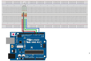
with a special type of LED, this is known as a RGB LED. What RGB stands for is
RED,GREEN,BLUE and that means this single LED can alternate between displaying
RED,GREEN and BLUE lights. Let us take a look at the RGB LED and how we should
connect it to the Arduino using a Breadboard.
After we are done with the circuit, it’s time to write the
code. I encourage you to learn how to write the codes yourself so I won’t be
giving links to where you can just download the codes until we reach later
parts. For now, get yourself used to typing the codes so you know the syntax.
The code we will be using is similar to the code of the Traffic light project
and we just want to test that the RGB LED works well by displaying each colour
light one after the other. In the code, the GREEN light comes first, then the
BLUE and the RED lastly.
I endeavor you to also try out the Emergency/Police light
program using this single RGB LED. Here, you won’t need to use the GREEN
terminal of the RGB LED since the Emergency or Police LIGHT is just RED and
BLUE. What else could you use this LED for??, think about it and try it!. Ciao.


No comments:
Post a Comment